


Published on Apr 02, 2024
Many of the ordinary brakes, which are being used now days stop the vehicle by means of mechanical blocking. This causes skidding and wear and tear of the vehicle. And if the speed of the vehicle is very high, the brake cannot provide that much high braking force and it will cause problems. These drawbacks of ordinary brakes can be overcome by a simple and effective mechanism of braking system 'The eddy current brake'. It is an abrasion-free method for braking of vehicles including trains.
It makes use of the opposing tendency of eddy current
Eddy current is the swirling current produced in a conductor, which is subjected to a change in magnetic field. Because of the tendency of eddy currents to oppose, eddy currents cause energy to be lost. More accurately, eddy currents transform more useful forms of energy such as kinetic energy into heat, which is much less useful. In many applications, the loss of useful energy is not particularly desirable. But there are some practical applications. Such an application is the eddy current brake.
For additional safety on long decants in mountain area
For high speed passenger and goods vehicle
Eddy current brakes are best substitutes for ordinary brakes, which are being used nowadays in road vehicles even in trains, because of their jerk-free operation. In mountain areas where continuous braking force is needed, for a long time, the eddy current braking is very much useful for working without overheating. Eddy current brakes are very much useful for high-speed passengers and good vehicles. It can also be used to slow down the trolleys of faster roller coasters.
Eddy current brake works according to Faraday's law of electromagnetic induction. According to this law, whenever a conductor cuts magnetic lines of forces, an emf is induced in the conductor, the magnitude of which is proportional to the strength of magnetic field and the speed of the conductor. If the conductor is a disc, there will be circulatory currents i.e. eddy currents in the disc. According to Lenz's law, the direction of the current is in such a way as to oppose the cause, i.e. movement of the disc.
Essentially the eddy current brake consists of two parts, a stationary magnetic field system and a solid rotating part, which include a metal disc. During braking, the metal disc is exposed to a magnetic field from an electromagnet, generating eddy currents in the disc. The magnetic interaction between the applied field and the eddy currents slow down the rotating disc. Thus the wheels of the vehicle also slow down since the wheels are directly coupled to the disc of the eddy current brake, thus producing smooth stopping motion.
Essentially an eddy current brake consists of two members, a stationary magnetic field system and a solid rotary member, generally of mild steel, which is sometimes referred to as the secondary because the eddy currents are induced in it. Two members are separated by a short air gap, they're being no contact between the two for the purpose of torque transmission. Consequently there is no wear as in friction brake.
Stator consists of pole core, pole shoe, and field winding. The field winding is wounded on the pole core. Pole core and pole shoes are made of east steel laminations and fixed to the state of frames by means of screw or bolts. Copper and aluminium is used for winding material the arrangement is shown in fig. 1. This system consists of two parts.
1. Stator
2. Rotor
It is suppored frame members of the vehicle chassis. It has introduced magnetic poles energized by windings. Current is supplied to the winding from the battery.
It is a rotating disc, which is fitted on the line of crankshaft with small air gap to stator. When disc rotates a flux change occur in the section of the disc passing the poles of stator. Due to the flux change there is a circulatory or eddy current in the disc around the magnetic lines of force. The effect of this eddy current induces ‘N’ and ‘S’ poles at the surface of the disc. Then there will be a ‘drag’ or braking effect in between eddy current induced poles and magnetic poles in the stator. By changing current from the battery we can change the braking force. In this breaking system kinetic energy of the vehicle is converted to heat and this heat is dissipated through the rotating disc.
Total resistance of field winding
R = L/A
where, L = total length of field winding in meter.
= Resistivity of the wire in ohm meter
A = the area of cross section of field winding in m2
Total no: of terms = total length /mean length of one term
The rotor is a rotating disc on shaft, which is placed very near to the stator with small air gap (1 mm to 2 mm). Rotating disc may be one or both side of stator.
The two units have common ring member, poles cores on which winding are provided being fixed to ring number. If a malleable casting is employed, then the pole core could be cast integrally with the right. After fitting the windings on the cores, poles shoes are fitted to provide pole faces of appropriate shape and area. The rotor disc should be provided with properly designed fins for faster heat removal.
The magnetic circuits of the two units are substantially the same, non-undue and thrust would be imposed on the motor bearings. Slight axial displacement of rotor could however, cause quite appreciable discrepancy, the air gap of two units. The effect would be to increase the magnetic pull in one air gap and diminish it on other which could give to rise to excessive and thrust on rotor bearing to overcome the inherent defect, the air gaps of both units could be put in series by making the central number non magnetic and providing a continues pole core for each pair axially opposite poles. This modification could possibly reduce the length of the combined pole course or permits a larger winding length.
The maximum diameter of the eddy current brake is decided by
1. The spacing of vehicle chassis frame.
2. Vehicle floor clearance
When the vehicle is moving, the rotor disc of eddy current brake which is coupled to the wheels of the vehicle rotates, in close proximity to stationary magnetic poles. When we want to brake the vehicle, a control switch is put on which is placed on the steering column in a position for easy operation.
When the control switch is operated, current flows from a battery to the field winding, thus energizing the magnet. Then the rotating disc will cut the magnetic field. When the disc cuts the magnetic field, flux changes occur in the disc which is proportional to the strength of the magnetic field. The current will flow back to the zero field areas of the metal plate and thus create a closed current loop like a whirl or eddy. A flow of current always means there is a magnetic field as well. Due to Lenz’s law, the magnetic field produced by the eddy currents works against the movement direction. Thus instead of mechanical friction, a magnetic friction is created. In consequence, the disc will experience a “drag” or the braking effect, and thus the disc stops rotation. The wheels of the vehicle, which is directly coupled to the disc, also stop rotation. Faster the wheels are spinning, stronger the effect, meaning that as the vehicle slows, the braking force is reduced producing a smooth stopping action.
The control switch can be set at different positions for controlling the excitation current to several set values in order to regulate the magnetic flux and consequently the magnitude of braking force. i.e. if the speed of the vehicle is lpw, a low braking force is required to stop the vehicle. So the control switch is set at the lowest position so that a low current will be supplied to the field winding. Then the magnetic field produced will be of low strength, so that a required low braking force is produced.
When the control switch is operated during the standby position of the vehicle, the magnet will be energized and magnetic field is created. But since the wheels are not moving, magnetic lines of force are not cut by it, and the brake will not work. However, a warning lamp is provided on the instrument panel to indicate whether the brake is energized. This provides a safe guard for the driver against leaving the unit energized.
When control switch is put in any one of the operating positions, the corresponding conductor in the contractor box is energized and current flows from the battery to the field winding to the contractor box. This current magnetizes the poles in stator, which placed very near to the rotor. When rotor rotates it will cut magnetic lines and eddy current will set up in the rotor. The magnetic field of this eddy current produces a breaking force or torque in the opposite direction of rotation disc. This kinetic energy of rotor is converted as heat energy and dissipated from rotating disc to surrounding atmosphere. Current in the field can change by changing the position of the controls switch. Thus we can change the strength of the braking force.
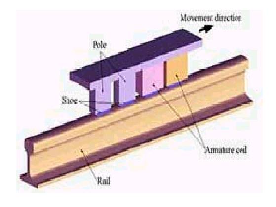
In the case of trains, the part in which the eddy current is induced is rail. The brake shoe is enclosed in a coil, forming an electromagnet. When the magnet is energized, eddy currents are induced in the rail by means of electromagnetic induction, thereby producing braking action.
There are two types of eddy current brakes according to the method of excitation.
1.Electrically excited eddy current brake
2.Permanent magnet eddy current brake
Electrically excited eddy current brakes are abruption-free method for braking. In high-speed trains they offer a good alternative to the mechanical rail brakes which are being used now a days. During braking, the brake comes in contact with the rail, and the magnetic poles of brakes are energized by a winding supplied. Magnetic poles of brakes are energized by a winding supplied with current from the battery. Then the magnetic flux is distributed over the rail. The eddy currents are generated in the rail, producing an electromagnetic braking force. This types of braking need an additional safety power supply when there are breakdowns in the electrical power supply.
| Are you interested in this topic.Then mail to us immediately to get the full report.
email :- contactv2@gmail.com |
