

Published on Nov 30, 2023
In this paper we describe various methods of boundary layer control which can be applied on bluff body like a busto reduce the form drag on it. We resorted to three different methods for form drag reduction on that body namely:
1. Streamlining the shape of body
2. Providing bypass in the slotted wings
3. Rotating boundary in the direction of flow
Keywords : Streamlining, Drag Reduction
Buses, vans or some other bluff shaped vehicles are known to be aerodynamically inefficient compared to other ground vehicles due to their large frontal areas and bluff body shapes. The inefficient aerodynamic shape results in excessive drag which leads to elevated fuel consumption rates thus contributes to heavy vehicles aerodynamic drag are mainly due to pressure drag also known as form drag. It is estimated that the pressure drag on heavy vehicles accounts to more than 80% of the total aerodynamic drag, with frictional drag accounting for the remaining 20%.Hence by applying various methods of boundary layer control we could reduce the drag force on bluff bodies like buses.
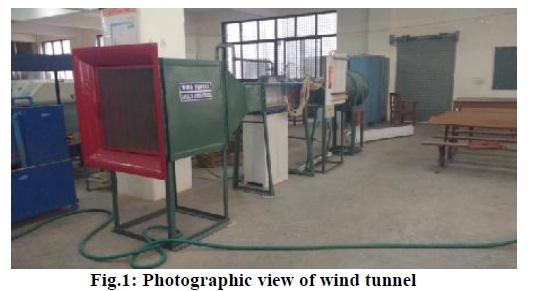
Characteristics of Wind Tunnel:
Open air wind tunnel
It’s test section has dimension of 100cm × 35cm × 35cm
In Fig. 1 depicted photograph is of the wind tunnel used at Hydraulics laboratory of SIT,Tumakuru
When the boundary layer separates from the surface certain portions adjacent to the surface has a back flow and eddies are continuously formed in this region and hence continuous loss of energy takes place. Thus separation of boundary layer is undesirable and the following are its preventive methods:
I. Streamlining the shape of body.
II. Providing a bypass in the slotted wing.
III. Rotating boundary in the direction of flow.
When the shape of a body is bluff it experiences very high drag force opposite to the direction of its motion.Drag force acting on a body is given by ��=����∗1/2*D*V2 (projected area)
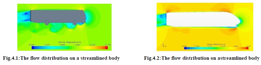
The separation of flow taken at the sharp edge of the body.By streamline the shape of the body as shown in figureabove the value of coefficient of drag reduces thus theresistive force acting on the bluff body reduces. Fig 4.1 &4.2 shows the flow distribution on a streamlined body
A slot is created on the edge of side and preferably on thetop of body. Air with high velocity pass through slotspushes the formation of separation point downstream .Thiscause the reduction in form drag (pressure drag) of the body, resulting in the reduced value of the body drag
The boundary layer owes its existence to the velocity difference between the wall and the outer flow; it could be eliminated by ensuring that the velocity difference is reduced. This can be achieved by moving the wall along the flow. A moving wall can be most simply realized in the rotation of a circular cylinder in a flow as shown in a Fig5. On the upper side where the direction of flow and the direction of rotation are same, the separation of the boundary layer is shifted to a downstream move.
Wind tunnel is used to determine pressure variation, drag and lift, which is being acted upon various models like aero plane wing, cylinder, rectangular blunt model, bowl, car, tipper and various bus models fabricated using boundary layer control concept. Wind tunnel comprises of differential manometer and 12 pressure gauge tubes. The wind tunnel had a digital simulator which gave the value of drag and lift force acting on the bluff bodies. The models are kept in the wind tunnel (central chamber) where the current of air flows through the tunnel and changes its motion due to presence of body. The tubes from the pressure gauge are connected to pressure holes of the models like aerofoil, cylinder etc. The readings of the lift and drag coefficients from the wind tunnel are tabulated by using drag measuring instrument. The manometer readings are maintained between 1 to 3cms and the readings are tabulated separately. By using the formulae mentioned below and the values obtained from the reading, we can find out velocity, drag, liftand Reynolds’s number.
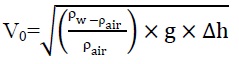
where,
V0= Velocity of the particles flowing in wind tunnel in ‘m/s'.
����= density of water in kg/m3= 1000 kg/m3. ��������= density of air in kg /m3 =1.225kg/ m.
g = acceleration due to gravity= 9.81 m/s2.
Δh = difference in monometer reading as noted down in tabular column.
Drag (N) = Drag (Kg) × 9.81 (N)
Lift (N) = Lift (Kg) × 9.81 (N)
Reynolds’s number: Re= ��air × Vo × dμ
where,
Re = Reynolds’s number
��������=density of air in kg /m3 =1.225kg/ m3
V0 = velocity of the particles flowing in wind tunnel in m/s
d = effective length of model opposite to wind direction in m.
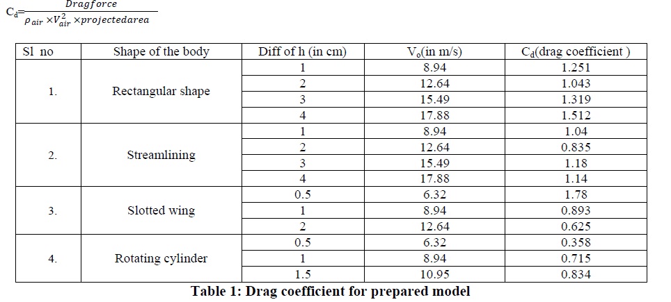
Drag measurement
On stream line body with rotating cylinder
On stream line body with rotating cylinder with slots
