


Published on Apr 02, 2024
To investigate the relation between the ratio of:-
1. input and output voltage
2. number of turns in secondary coil of self designed transformer
A Transformer based on the Principle of mutual induction according to this principle, the amount of magnetic flux linked with a coil changing, an e.m.f is induced in the neighbouring coil.
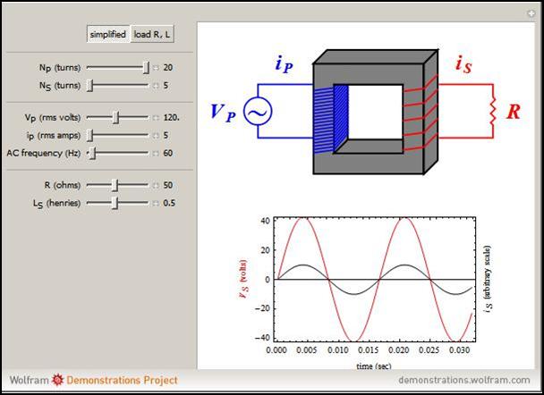
A transformer consists of a rectangular shaft iron core made of laminated sheets, well insulated from one another. Two coils p1 & p2 and s1 & s2 are wound on the same core, but are well insulated with each other. Note that the both the coils are insulated from the core, the source of alternating e.m.f is connected to p1p2, the primary coil and a load resistance R is connected to s1 s2, the secondary coil through an open switch S. thus there can be no current through the sec. coil so long as the switch is open.
For an ideal transformer, we assume that the resistance of the primary & secondary winding is negligible. Further, the energy loses due to magnetic the iron core is also negligible.
When an altering e.m.f. is supplied to the primary coil p1p2, an alternating current starts falling in it. The altering current in the primary produces a changing magnetic flux, which induces altering voltage in the primary as well as in the secondary. In a good-transformer, whole of the magnetic flux linked with primary is also linked with the secondary, then the induced e.m.f. induced in each turn of the secondary is equal to that induced in each turn of the primary. Thus if Ep and Es be the instantaneous values of the e.m.f.’s induced in the primary and the secondary and Np and Ns are the no. of turns of the primary secondary coils of the transformer and
Dфь / dt = rate of change of flux in each turnoff the coil at this instant, we have
Ep = -Np dфь/dt -----------------(1)
And
Es = -Ns dфь/dt ----------------- (2)
Since the above relations are true at every instant, so by dividing 2 by 1, we get
Es / Ep = - Ns / Np ----------------(3)
As Ep is the instantaneous value of back e.m.f induced in the primary coil p1, so the instantaneous current in primary coil is due to the difference (E – Ep ) in the instantaneous values of the applied and back e.m.f. further if Rp is the resistance o, p1p2 coil, then the instantaneous current Ip in the primary coil is given by Ip = E – Ep / Rp
E – Ep = Ip Rp
When the resistance of the primary is small, Rp Ip can be neglected so therefore
E – Ep = 0 or Ep = E
Thus back e.m.f = input e.m.f
Hence equation 3 can be written as
Es / Ep = Es / E = output e.m.f / input e.m.f = Ns / Np = K
Where K is constant, called turn or transformation ratio.
In a step up transformer
Es > E so K > 1, hence Ns > Np
In a step down transformer
Es < E so K < 1, hence Ns < Np
If Ip = value of primary current at the same instant t
And Is = value of sec. current at this instant, then
Input power at the instant t = Ep Ip and
Output power at the same instant = Es Is
If there are no losses of power in the transformer, then Input power = output power Or
Ep Ip = Es Is Or
Es / Ep = Ip / Is = K
In a step up transformer
As k > 1, so Ip > Is or Is < Ip
i.e. current in sec. is weaker when secondary voltage is higher.
Hence, whatever we gain in voltage, we lose in current in the same ratio. Similarly it can be shown, that in a step down transformer, whatever we lose in voltage, we gain in current in the same ratio. Thus a step up transformer in reality steps down the current & a step down transformer steps up the current.
Observe and identify the schematic and rating of the step down transformer to be installed. Remove the terminal connection box cover placed at the lower side of the transformer. Only the high amperage types will have this enclosure, while lower powered transformers will have an exposed screw terminal.
Know termination identification follows for all step down transformers: H1, H2, H3 and H4 signify the high voltage side or power feed end of the transformer. This holds true regardless of the size of the transformer. Interconnection of the transformer will vary depending on the manufacturer and voltage used for feeding the transformer.
Terminate the feed power wires first by cutting the wires to length. If you are using large wire lugs be sure to take into consideration the length of the lug and the amount of wire that can be inserted into the female crimp area.
Strip back the outer insulating of the wires with the pocketknife or wire strippers. Insert the eye ring or wire lug over the bare copper wire and crimp the connection device, using the appropriate-size crimper, permanently to the wire.
Terminate the high side, high voltage of the step down transformer. If the high side terminals are bolts, be sure to follow any torque requirements that are listed by the manufacturer.
Terminate the low side, low voltage of the transformer. Note these terminals will be identified by X1, X2, X3 and X4. Again follow the manufacturer's individual schematics for that particular type of transformer. Note that on small control transformers there will only be an X1 and X2. X1 is the power or "hot" side and X2 is generally the grounding and neutral portion of the low voltage.
Terminate the small control transformer for X1 and X2. X1 will go directly to the control circuit after passing through a small fuse that is rated for the circuit. X2 will be terminated not only to the neutral side of the control circuit, but the grounding safety as well. In other words, the X2 side of the small control transformer must be tied to the grounding system of the electrical circuit.
Replace all covers on the transformer and any enclosures that protect you from electricity. Apply the high voltage to the transformer by switching on the feeder power circuit. Turn on the low side safety circuit control.
Use a volt meter to test for proper voltage on the step down side of the transformer. It should be the same that is listed on the specs tag provided by the manufacturer.
Following are the major sources of energy loss in a transformer:
1. Copper loss is the energy loss in the form of heat in the copper coils of a transformer. This is due to joule heating of conducting wires.
2. Iron loss is the energy loss in the form of heat in the iron core of the transformer. This is due to formation of eddy currents in iron core. It is minimized by taking laminated cores.
3. Leakage of magnetic flux occurs inspite of best insulations. Therefore, rate of change of magnetic flux linked with each turn of S1S2 is less than the rate of change of magnetic flux linked with each turn of P1P2.
4. Hysteretic loss is the loss of energy due to repeated magnetization and demagnetization of the iron core when A.C. is fed to it. 5. Magneto striation i.e. humming noise of a transformer.
1. The output voltage of the transformer across the secondary coil depends upon the ratio(Ns/Np) with respect to input voltage.
2. The output voltage of the transformer across the secondary coil depends upon the ratio(Ns/Np) with respect to input current.
3. There is a loss power between input and output coil of a transformer.
