

Published on Nov 30, 2023
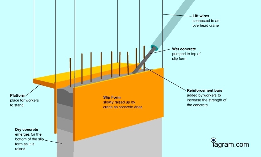
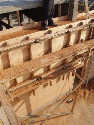
On the basis of construction drawings, we plan the performance of sliding formwork with drawings and slide profiles for openings and embedded items. The moulds, which are 1.1 metres high, are made of wood covered with a 1 mm steel sheet. According to the load and design in question, we fit lifting yokes and hydraulic jacks. The jacks are fitted to scaffolding that is gradually moved as the slide progresses. Lasers are used for vertical checking, while spirit levels are used for horizontal checks. The work platform itself is fitted to beams with a hanging platform mounted below. During operation, all the jacks are controlled by a central unit. Each lift normally raises the slide 20-25 mm. Casting and reinforcement work is normally performed continuously as the sliding formwork works its way up. The intended hardening front is approximately 90 cm, which means that this is located around 20 cm from the bottom edge of the mould. The setting time is regulated by additives (acceleration/retardation) so that it matches the progress of the mould. The normal slide rate is 2.5-3.5 metres per day, but depending on the construction project, we can produce 7-8 metres per day
As for all projects, success depends on good planning. Choosing to use sliding formwork for construction early in the planning process means that the project can be prepared for this technique. Important parameters such as concrete quality must be checked. Unintended variations in the concrete quality must be avoided, and efficient, accurate control of the concrete setting time is particularly important. Moreover, reinforcement should be standardised with as few posts as possible, and particular attention must be paid to the distance between the reinforcement bars, bar length and the shape of angles and bows. If required, tensioning cables are fitted simultaneously with the other work, so stringent requirements apply to pre-positioning and preparation. Openings and embedded items must also be adapted to the sliding casting method, as such items must not extend beyond the wall surface of the construction. Normally, such items need to be 15-20 mm thinner than the wall(s) in question. Sliding profiles with the correct contour height and position need to be prepared.
Civil engineering course put more attention to concrete and reinforcement while almost ignoring the major component like formwork. No attention is paid to economic design of formwork. Formwork costs approximately 10% of the total cost of the construction projects but at the same time sheltering/scaffolding involves major capital investment.
The construction industry today lacks Engineers who can design a good formwork system. There are enough Engineers to do concreting, reinforcement and a structural design but there are not many to improve upon the formwork.The procedures so far has been mainly hit and trial at least for the smaller construction companies. In spite of being such a major capital cost component, no enough research has been done to minimize the cost of formwork.
Ever since man began to building structures he has to cope up with technical limitation, practical problems limit the height of sky crapper and lengths of bridge. To constantly challenge the limits of what we can achieve, new techniques are created and discovered by people in all fields of construction.
The increasing shortage off skilled carpenters, the cost of timber and economic disadvantages of economic disadvantages of traditional purpose built forms have made the use of SLIP FORMING is necessary. So that revolutionary technique called SLIP FORMIG is in introduced.

Slip Forming is technique of construction using mechanized formwork. Slip forming is process of continuous lifting of formwork by a hydraulic system of jacks and pumps
A technique that was first used in America in 1910 gained prominence and technical advance in Europe in 1960. The earlier systems were manually operated and cumbersome. But as time passed it has gained new dimensions. This slip forming technique the unprecedented synthesis of maximum output and minimum input.
In India since, 1982 SLIPCO CONCTRUCTION (P) LTD LARSEN AND TURBO has been pioneers in this field. For LARSEN AND TURBO “NO STRUCTURE IS COMPLICATED BY SLIP FORMING.
Also one example of ASHOKA GROUP who had constructed a bridge near Pandharpur in 38 days was record .it was just possible due to technique of SLIP FORMING.
It is characterized by one-meter high forms for the whole cross section or part of it which are lifted in an interrupted continuous sliding process according to the setting time of concrete. The slip forms are firmly connected to the working plat form and avoid expensive erection and dismantling of fixed scaffolds. The lifting of the form is erected uniformly and simultaneously in intervals and continuous single lifting in steps of 2.5 cm by means of hydraulic lifting system.
The biggest benefit we provide is the rapid installation time. With a slide speed of 2.5-3.5 metres per day, you can be sure of a shorter construction time and, as a result, reduced costs.

A sliding casting process is continuous, so there will be no casting joins. This is a great benefit, particularly in the case of watertight constructions
The system has been developed over 40 years and can therefore handle complex constructions with the highest levels of confidence
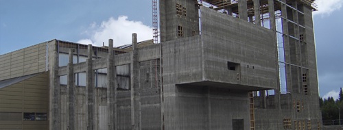
Such constructions may involve openings of various sizes, embedded items, reinforcements, jumps, conical shapes, continuous reduction of wall thickness, and so on.
Sliding formwork is a safe construction method that does not require major crane lifts and the associated risks. It also means that the system is largely unaffected by the weather, and sliding casting can continue even in high winds.
1. Chimney.
2. Silos.
3. Towers.
4. Lift core shafts.
5. Piers.
6. Oil tanks.
7. In framed structure also.
8. Wall- one & two sided
9. Cast dam
10. Wind tunnel
1. Center point.
2. Starter / kicker.
3. Form.
4. Yokes.
5. Normal brackets.
6. Central control system.
7. Jack holder.
8. Yoke leg clsmp.
9. Panel clamp.
10. Waler cleat plates.
11. Working platform.
12. Lifting equipment.
13. Pump.
14. Jack.

1. Simple and versatile.
2. Takes you to any height.
3. Copes with every wall structure.
4. The system can be erected using unskilled labors.
5. This helps in quick and easy assembling and dismantling.
6. It has a dominant influence on the appearance and accuracy of finished concrete.
7. There is minimum consumption of timber and steel in the formwork.
8. It gives a monolithic structure without vertical and horizontal construction joints.
Faster construction.
Economical construction.
Quality construction.

Ordinary Portland Cement conforming to IS 269 or an equivalent standard is suitable for all slip forming work through the use of a rapid hardening of slow setting cement is some special slip form works is not ruled out.
One very important criteria for the cement in slip form work is it’s initial and final setting time on which the sliding speed and early age characteristics of the concrete depend on a large extent it is very important and very essential to ensure that variations in the setting times of the cement used are within narrow limits in order that the mixed design and sliding speed can be planned properly.
Another very important aspect of slip forming is the frictional resistance between the concrete and the moving formwork.
Among other factors, the correct shape and grading of fine particles will ensure the least possible friction between the forms and the concrete. The ideal course aggregate is rounded in shape and, hence, natural gravel would preferred.
The maximum size of aggregate generally depends on the cover and on the spacing of reinforcement, and it will also depend to some extend on the method of transportation, i.e. by crane or by pumping. As a general rule, one can assume that restriction of the except for thin section.
Another important aspect of the course aggregates is their water absorption. Some aggregate, such as lime stone or sand stone, tend to observe a substantial quantity of water.
Generally it is better to avoid such aggregates since water absorption may tend to make the mix very stiff and prevents the formation of usual thin film of mortar or such cases, friction is high and hence, detrimental the movement of forms, resulting in an inferior surface of the concrete.
The presence of clay, silt and dust in excessive quantities in aggregate will also increase water demand, which if not provided for will results in reduced workability.
As a general rule, natural sand is chosen as a fine aggregate. Too fine sand may result in thin film of mortar at the interface of the form and the concrete surface. This will have the tendency to take of during the subsequence finishing operation and will result in surface blemishes. To course a grading will tend to give a very rough surface and finishing of the surface becomes extremely difficult.
1. Retards delay the setting of cement and hardening of concrete and are particularly useful in warm weather. They also assist in making of the deficiencies in fine aggregate greadings.
2. Plasticizers increase work ability and are available in normal, accelerating and retarding grades.
The following aspects have to be taken in to account while designing the mix for slip formed work.
1. The concrete at the time deshuttering is in a semi plastic state as it leaves the forms at leaves the forms a very early age (4 to8 hrs) and requires a wet surface to permit a good surface finish.
2. The concrete should attain sufficient strength at 4to 8 hrs to withstand the vertical load of the concrete column above and the horizontal forces induced by wind and other loading on slip form shuttering .
3. After leaving the shuttering and being finished the design strength at 28 days.
4. The concrete should have sufficient workability to enable placing in the form and compaction easily.
5. The mix should not be harsh and made with aggregates containing enough fine particles and having a continuous grading in order to reduce the friction between the forms and concrete.
6. The concrete should be easily amenable to the mode of transportation i.e. crane, hoist, pump, etc.
7. The concrete should not bleed excessively or segregate.
8. The concrete should give a uniform color and finish on the surface as it leaves the forms.
9. The stiffening time of concrete should be compatible with the planned speed of slipforming.
Cold weather is defined as a time span of more than three consecutive days during which the average daily temperature remains below 5ْ C When the temperature remains consistently above 10ْْ C for more than 12 hours during any 24-hr period, the requirements for cold weather concreting are no longer applicable.
The adverse effect of low temperature is as follows.
1. Delayed setting and retardation in development of concrete strength.
2. Increase in the period of hardening and delay in removing of formwork
3. Reduced initial strength.
4. Freezing at early stages.
5. Thermal shocks.
6. Loss of concrete strength up to 50%
For cold weather concreting it is recommended to use. Rapid hardening Portland cement be used, which because of its higher tri-calcium silicate content will also generate higher heat of evaluation at critical early stages. The early high strength thus obtained will permit a shorter period of protection and quicked turn around of formwork and scaffolding.
It must be ensured that the aggregates are free of ice, Snow and frozen lumps and they are protected against frost.
Both the aggregates and water may have to be heated so that the resultant concrete as placed has a minimum temperature as laid down in the standards.
The initial temperature of concrete as placed should never be less than 50ْC.
To minimize fluctuations in temperatures and slump of concrete from one batch to another, the mixing water should be supplied at a uniform controlled temperature and in an adequate quantity. The slump should not exceed 100mm to minimize bleeding and accelerate setting
Hot weather can be defined as combination of high air temperature, low relative humidity and wind velocity tending to impair the quality of fresh or hardened concrete
Some of the problems that can be faced in hot weather concreting are follows:-
1. Difficulty in control of entrained of air
2. Rapid evaporation of mixing water
3. Rapid slump loss
4. Accelerated set.
5. Reduced strength
6. Increased permeability
7. Greater dimensional changed on cooling have hardened concrete.
Proper attention should be paid to mixing as the process of mixing provides heat to mix. The effect of mixer surface to the sun should be minimized by painting and light colors and continuously spraying with cold water.
The period between mixing and delivering should be kept as small as possible as cement hydration, temperature loss, aggregate and grinding and loss of air all increases with passage of time. Preparations must be made to transport, place, consolidate and finish the concrete at the fastest possible rate. Increases of prevailing aried wind temporary windbreaks must be provided to reduce the heat.
The sub grade should be moist but free of standing water and soft sports at the temperature of concreting. For best overall results the temperature of concreter should not exceed 32deg Celsius and should be kept uniform under extreme circumstances, concreting may be carried out only at the late afternoon and evening
With the invention of slip forming technique and due to speedier completion of work by the technique, there are substantial savings in cost in terms of wages and interest .This technique has no comprises against quality control and Homogeneity of structure.
The cost saving will not appear automatically just because slip forming has been used .This technique has a lot of scope for improvement .But it can be adapted for tall framed structure. For slip forming work ordinary concrete of equally M20 &M25, rarely M30. Generally Portland cement is used for concreting. Fast setting cement in special cases work during winter and slip form progress is chosen. After dismantling the slip form components it can be used for span more than 25 years.
Thus slip form system involves:-
QUALITY CONSTRUCTION.
ECONOMICAL CONSTRUCTION.
SPEEDIER CONSTRUCTION
1. Indian Concrete Journal – March – 1998.
2. Indian Concrete Journal – March – 1999.
3. Indian Architects & Builders – March – 2000.
4. Article on construction of tunnels-By D .G. Diwate, Chief Project Manger; Konkan Railway Corporation Ltd;
5. Article on aggregate crushing system- By Ajit Pradhan & Sandeep Bhattacharjee ICJ June 2000.
6. Article on construction of Viaducts - By S. K. Dharmadhikari Deputy Project Manager Hindustan construction Co . Ltd in ICJ June 2000
7. Progress of privatization in highways By Prafulla Kumar , Indian Highways ICJ June 2000
| Are you interested in this topic.Then visit the below page to get the full report |